ring (normally called the RETAINING RING).
The centering ring is used as a reinforcement to
prevent blowouts. The filler piece is replaceable.
When renewing a gasket, you should remove this
piece from the retaining metal ring and replace
it with a new filler. Do not discard the solid metal
retaining outer or centering ring unless it is
damaged. You can compress the gaskets to the
thickness of the outer or centering ring.
When renewing a gasket in a flange joint, you
must exercise special precautions when breaking
the joint, particularly in steam and hot water lines,
or in saltwater lines that have a possibility of direct
connection with the sea. Be sure to observe the
following precautions:
1.
2.
3.
4.
5.
6.
No pressure is on the line.
The line pressure valves, including the
bypass valves, are firmly secured, wired
closed, and tagged.
The line is completely drained.
At least two flange-securing bolts and nuts
diametrically opposite remain in place until
the others are removed, then slackened to
allow breaking of the joint, and removed
after the line is clear.
Precautions are taken to prevent explosions
or fire when breaking joints of flammable
liquid lines.
Proper ventilation is ensured before joints
are broken in closed compartments.
These precautions may prevent serious ex-
plosions, severe scalding of personnel, or flooding
of compartments. You should thoroughly clean
all sealing and bearing surfaces for the gasket
replacement. Check the gasket seats with a
surface plate, and scrape as necessary. This
affords uniform contact. Replace all damaged
bolt studs and nuts. In flange joints with raised
faces, the edges of gaskets may extend beyond the
edge of the raised face.
O-RINGS
Another method of preventing leakage in fluid
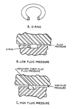
systems is by use of O-ring seals. Figure 9-64
shows an O-ring seal with two cross-sectional
views. An O-ring is a doughnut-shaped, circular
seal (view A of fig. 9-64) that is usually a molded
rubber compound. An O-ring seal has an O-ring
mounted in a groove or cavity (usually called a
gland).
Figure 9-64.—O-ring seal with two cross-sectional views.
When the gland is assembled (view B of fig.
9-64), the O-ring cross section is compressed.
When installed, the compression of the O-ring
cross section enables it to seal low fluid pressures.
The greater the compression, the greater is the
fluid pressure that can be sealed by the O-ring.
The pressure of the O-ring against the gland
walls equals the pressure caused by the recovery
force of the compressed O-ring plus the fluid
pressure.
The fluid pressure against the walls of the
gland and the stiffness of the O-ring prevent fluid
from leaking past the O-ring. If the downstream
clearance is large, the O-ring is forced into this
clearance (view C of fig. 9-64). The stiffness of
the O-ring material prevents the O-ring from
being forced completely through the downstream
clearance unless that clearance is abnormally large
or the pressure is excessive.
O-rings are commonly used for sealing because
of their simplicity, ruggedness, low cost, ease of
installation, ease of maintenance, and effective-
ness over wide pressure and temperature ranges.
9-44


