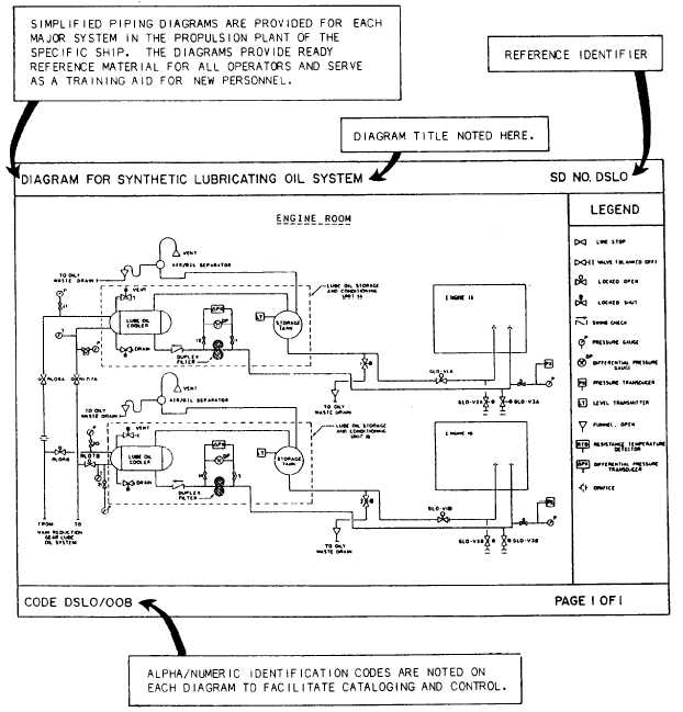
Figure 1-7.—Sample training diagram.
the various plant operating conditions.
l
This diagram is also provided in the stage
II electrical documentation.
System alignment diagrams showing the
preferred initial and final alignment for
each engineering plant.
l
A diagram for equipment versus speed
requirement delineating the equipment
normally required for various ship speeds.
A diagram that shows the location of shore
service connections. This diagram traces
the connections for steam, electrical
power, feedwater, potable water, firemain,
and fuel oil.
Training diagrams (fig. 1-7) outlining each
major piping system to aid in plant
familiarization and training of personnel.
These diagrams indicate the relative loca-
tions of lines, valves, and equipment.
1-15

