DIGITAL IC CONVENTION
The theorems of Boolean algebra are applied to the
AND, OR, or NOT logic gates, or any logic gates, on
the basis that only two possibilities exist as far as any
statement of their outputs is concerned. Their
statements are either true or false. A 1 symbol is true
and a 0 symbol is false. In digital logic circuits, the 1
and the 0 are represented by different voltage levels and
the particular logic convention must be specific. When
the logic levels for a computer are defined, the two
voltages will be relative to each other when determining
if it is positive or negative logic.
Digital computers can use either positive or
negative logic.
There are advantages and
disadvantages to both types. Depending on its
application in a system, the specific logic convention is
consistent throughout the entire computer. The concept
of positive and negative logic is more than a matter of
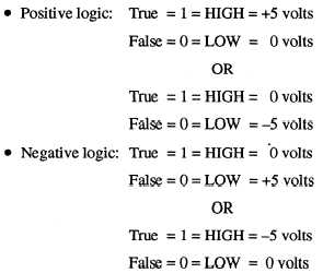
voltage levels. Positive logic indicates that the voltage
level for a 1 will be more positive than the voltage level
for a 0. Negative logic indicates that the voltage level
for a 1 will be more negative than the voltage level for
a 0. The following examples are given:
When it is necessary to use apiece of test equipment
in performing maintenance on the computer, you will
need to know the logic convention the computer uses.
DIGITAL LOGIC GATE INPUT AND
OUTPUT WAVESHAPES
The waveshapes of the inputs and outputs of digital
logic gates are important when analyzing the operation
of digital logic gates. They can provide you valuable
information when you perform maintenance. All dig-
ital logic gates produce waveshapes on the input or the
output of the gate(s). The input and the output can be
monitored individually or they can be monitored at the
4-8
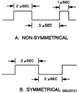
Figure 4-6.—Examples of waveshapes: A. Non-symmetrical;
B. Symmetrical.
same time. Learn what the waveshapes mean and learn
how to analyze them. Remember, the clock pulses and
timing signals play an important role in the operation of
the digital logic gates, combinational and sequential.
Waveshapes come in two types: non-symmetrical and
symmetrical. Refer to figure 4-6 for examples.
Three characteristics of waveshapes can play an
important role in your understanding of computers.
You can use them to monitor and/or analyze
waveshapes. The following examples of each will help
you see how they are calculated:
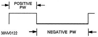
Pulse width (PW) —PW is the time interval
between specified reference points on the leading edge
and trailing edges of the pulse waveform. Pulse widths
are usually further defined as a positive PW and a
negative PW. Refer to figure 4-7 for an example.
Pulse-repetition time (PRT) —The PRT of a
signal refers to the time period from the starting point
of a repeating waveshape until the starting point of the
next repetition.
Refer to figure 4-8 for an example
measurement.
Figure 4-7.—Examples of pulse width (PW) measurements.


