are the symbols associated with the logic gates. The
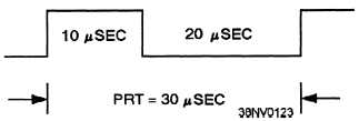
Figure 4-8.—Example of pulse-repetition time (PRT).
Pulse-repetition frequency (PRF) —The PRF of
a signal is the number times per second that a complete
cycle of the signal occurs and is expressed in hertz (Hz).
Learn the relationships between PW, PRT, and PRF.
They can be very helpful and can save you valuable time
when you analyze waveshapes. You can apply them to
non-symmetrical and symmetrical waveshapes. The
basic formula is as follows: PRF = 1/PRT.
Using figure 4-8, we can calculate the PRF. Since
the PRT is 30 msec, then using the formula would give:
PRF = 1/PRT= 1/30 msec = 33 kHz.
DIGITAL IC GROUPS
The basic building blocks of digital logic circuits
contained in a computer are logic gates. The logic
circuits contained in digital logic circuits can be
classified into two groups: combinational and
sequential.
Combinational digital logic circuits —The basic
building block for combinational digital circuits is the
logic gate.
Sequential digital logic circuits —The basic
building block for sequential digital circuits is the
flip-flop. Flip-flops are formed from variations of the
combinational digital circuits.
Digital Logic Gates
Digital logic gates are the basis for operations in a
digital computer.
The digital logic gates you will
encounter operate with binary numbers; hence, the term
digital logic gates. They are combinational and
sequential logic elements.
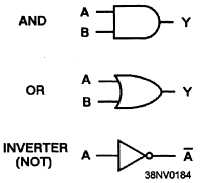
The AND, OR, and NOT logic gates are the basis
for all logic gates. These three logic gates are used in
different combinations and variations to form logic
gates that perform decision-making functions
throughout the computer. Included in our discussion
basic logic gates with their symbols are as follows:
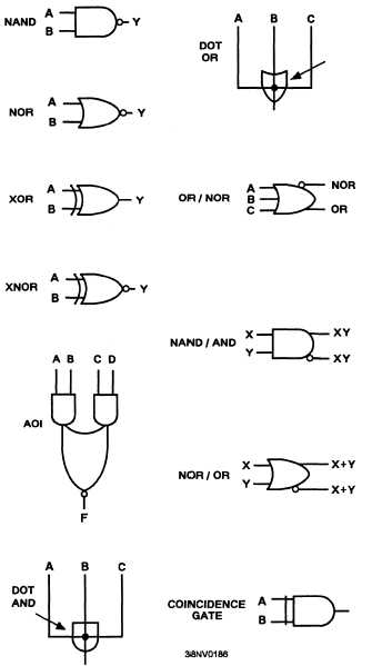
Simple variations of the three basic functions AND,
OR, and NOT gates are used as building blocks for the
other types of logic gates used in the computer. These
logic gates with their symbols are as follows:
4-9


