Data Set Ready (DSR) —A data set ready is sent
from the computer to the external device to notify the
external device that the computer is ready to transmit
data when HIGH.
Data Terminal Ready (DTR) —A data terminal
ready is sent from the external device to the computer
to indicate that the external device is ready to receive
data when HIGH.
Request to Send (RTS) —A request to send is
sent from the external device to the computer to indicate
that the external device is ready (HIGH) or busy
(Low).
Clear to Send (CTS) —A clear to send is sent
from the computer to the external device as a reply to
the RTS signal.
TRANSMIT BUFFER/TRANSMIT CON-
TROL. —The transmit control logic converts the data
bytes stored in the transmit buffer into an asynchronous
bit stream. The transmit control logic inserts the
applicable start/stop and parity bits into the stream to
provide the programmed protocol. A start bit is used to
alert the output device, a printer for instance, to get
ready for the actual character (bit). The signal is sent
just prior to the beginning of the actual character
coming down the line. A stop bit is sent to indicate the
end of transmission. The parity bit is used as a means
to detect errors; odd or even parity maybe used.
RECEIVE BUFFER/RECEIVE CONTROL.—
The receive control logic accepts the input bit stream
and strips the protocol signals from the data bits. The
data bits are converted into parallel bytes and stored in
the receive buffer until transmitted to the
microprocessor.
Line Drivers/Receivers
We discussed line drivers/receivers in chapter 4.
Their basic function is to drive and receive (detect) the
digital signal sent or received over a cable to other
external equipments (including computers). The line
drivers/receivers are designed to send and receive
signals over short and long distances using serial or
parallel format.
Large voltages or currents are
generated from small voltage or current using TTL or
MOS circuitry. The two types most commonly used
include single-ended and differential. The voltage
levels and current amounts sent and received are
dictated by the interface. The voltage and current
characteristics required are also dictated by the
interface. We discuss the voltage levels and some of
the characteristics when we cover I/O channel/port
configurations that include the various interfaces.
I/O INTERFACE FORMATS
There is a variety of serial and parallel I/O channel
formats that you may encounter as a technician. Do not
take for granted the type of interface a computer uses.
A single different pin in a connector or a different
voltage level used by a computer can make a vast
difference when you are performing maintenance.
Your computer’s technical manual will provide the
standards to be used with the cabinet and cable con-
nectors. They will match the standards that govern the
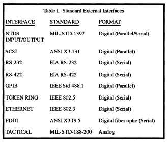
requirements for parallel and serial interfacing. Table
7-1, from MIL-STD-2036, General Requirements For
Electronic Equipment Specifications, provides you with
some of the accepted standard external interfaces. We
do not cover the General-Purpose Interface Bus (GPIB),
Fiber Distributed Data Interface (FDDI), and
TACTICAL. Other interfaces used but not listed in the
table include RS-449, Centronics Parallel, ST-506/412,
Enhanced Small Device Interface (ESDI), Integrated
Drive Electronic (IDE), and Enhanced Integrated Drive
Electronics (EIDE). We discuss signal designations in
more detail later in this topic under serial and parallel
I/O operations. First, let’s look at the various interfaces
and some of their applications and any unique
characteristics. As stated, each interface is governed by
a standard.
Table 7-1.—Standard External Interfaces from
MIL-STD-2036
7-21