source), and pin 17 (Receiver Signal Element
Timing—DTE source) are used for these purposes.
Pin 23, Data Rate Select —This entry according to
figure 7-25 looks like there should be two pins as-
signed, but actually it is either data rate select (DTE
source) or data rate select (DCE source). Some
modems, called dual-rate modems, allow switching
between two transmission speeds. Sometimes the
speed is selected automatically by the modem
during the initializing sequence, or it may be
selected by the transmitting DTE. The signal on pin
23 determines whether the modem uses the low or
high speed. Usually the modem at the calling end
sets the speed for the connection and informs its
DTE. The calling modem signals the speed to the
answering modem, which informs the called DTE
by activating data rate select (DCE source).
Pin 12, Secondary Data Carrier Detect
Pin 13, Secondary Clear to Send
Pin 14, Secondary Transmitted Data
Pin 16, Secondary Received Data
Pin 19, Secondary Request to Send —Some
modems are equipped with both primary and
secondary channels.
The five secondary signals
listed allow control of the secondary channel in the
same way as described for the primary channel
(pins 2, 3, 4, 5, and 8). In these modems, the
primary transmission channel usually has the
higher data rate, and the secondary channel
transmits in the reverse direction with a much lower
data rate, for example, 75 bps. Other signals that
could be used (depending on the interface used) but
not discussed include:
send common, receive
common, terminal in service, new signal, select
frequency, local loopback, remote loopback, test
mode, select standby, and standby indicator.
I/O PARALLEL DATA OPERATIONS
Parallel data operations provide a multiwire
communication path between the computer and one or
more peripheral equipments. Parallel data operations
use a request/acknowledge protocol. Generally speak-
ing, a parallel channel is designed to transfer all the bits
of a given byte or memory word, depending on the size
of the computer and interface requirements, simultane-
ously. There is a separate data path or line for each bit
that makes up the byte or word. The parallel channel
handles data bytes or words in the same manner as the inter-
nal workings of the computer. There is no requirement
to convert the byte or word to a sequential bit stream as
there is in serial channel operations. There is, however,
the need to drive or receive (detect) the digital signals
over the I/O cables. The IOA or line driver/receiver on
a pcb provides the means to accomplish this.
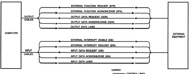
With parallel operations, there are two ways the
computer can communicate with each external device.
The computer can use a single cable to handle the
parallel input and/or output operations or two cables: an
input cable for the computer to receive information
from an external device and an output cable for the
computer to send information out to the same external
device. The two cables will constitute one channel.
Some computers can have up to 64 I/O channels. The
I/O channels are usually identified by the octal
numbering system. Thus, if you had a computer with
16 channels, the octal number assignments would be 08
through 178. Also, the channels are often arranged in
groups with 4 channels per group. The parallel channel
itself (fig. 7-27) consists of 8 or more data lines (8, 16,
Figure 7-27.—Example of parallel channel architecture (two cables).
7-31


