standard for implementing an RS-232 connection.
Now, let’s take spin-by-pin tour of the RS-232 interface
and look at the signals to see how they function.
RS-232 Pin Description
The 25 pins of the RS-232 have the following
functions:
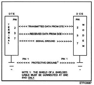
Pin 1, Protective Ground —is connected to the
equipment’s chassis and is intended to connect one
end of a shielded cable, if such a cable is used. The
shield of a shielded cable must NEVER be
connected at both ends. Shielded cable is used to
reduce interference in high-noise environments.
Pin 7, Signal Ground —is the common reference
for all signals, including data, timing, and control
signals.
In order for DCE and DTE to work
properly across the serial interface, pin 7 must be
connected at both ends. Without it, the interface
would not work because none of the signal circuits
would be completed.
Pin 2, Transmitted Data
Pin 3, Received Data —Pins 2 and 3 are the pins of
most importance; for if it weren’t for the data that
passes through them, the remaining pins would not
be needed. Data is normally transmitted in the
following manner. The DTE transmits data on pin
2 and receives data from the DCE on pin 3 as
described in figure 7-25 and shown in figure 7-26.
Figure 7-26 illustrates the absolute minimum
wiring required under the RS-232 interface for
normal DTE-DCE communication.
Pin 4, Request to Send
Pin 5, Clear to Send —Pins 4, 5, 6, and 20 are the
handshaking signals.
These pins establish the
communications link. Normally terminals cannot
transmit data until a clear to send transmission is
received from the DCE.
Pin 6, Data Set Ready
Pin 20, Data Terminal Ready —Data set ready is
used to indicate that the modem is powered on and
is not in a test mode (modem ready). In dial-data
or dial up applications, data terminal ready is used
to create the equivalent of an off-the-hook condition.
When the modem is in an auto-answer mode, the
DTR is activated in response to the ring indicator
and tells the modem to answer the incoming call.
Pin 8, Data Carrier Detect —The modem
activates the data carrier detect whenever it receives
a signal on the telephone line of sufficient strength
for reliable communications. Many types of DTE
Figure 7-26.—A typical DTE to DCE connection showing the
minimum wiring required under the RS-232 interface
standard.
require this signal before they will accept or trans-
mit data. In applications where no modem is present,
this pin is normally tied to pin 20, which in most
cases is activated whenever the DTE is powered up.
Pin 22, Ring Indicator —-The ring indicator signal
is the means by which the DCE informs the DTE
that the phone is ringing. All modems designed for
direct connect to the phone network are equipped
with auto answer. That is, the modem is able to
recognize standard ringing voltage, indicate the
ringing to the DTE, and answer (take the line
off-the-hook) when told to do so by the DTE. The
DTE tells the modem to answer the phone by
activating pin 20, data terminal ready.
The 10 pins and signals we have just described to
you are the ones most often used of those defined in the
RS-232 standard.
Pin 15, Transmit Clock
Pin 17, Receiver Clock
Pin 21, Signal Quality Detector
Pin 24, External C1ock —Synchronous modems
use the signals on these pins. Pins 15, 17, and 24
control bit timing. Pin 21 indicates that the quality
of the received carrier signal is satisfactory.
Because the transmitting modem must send
something (either a 0 or a 1) at each bit time, the
modem controls the timing of the bits from the
DTE. In turn, the receiving modem must output a
bit and associated timing whenever received. Pin
15 (Transmitter Signal Element Timing—DCE
7-30


