30, 32, 64, and so forth), and a number of control lines
for passing signals that govern the transfer of
information and coordinate operations of the computer
and the peripheral device. In most computers, the data
lines themselves are used to transmit control
information (external functions) to the peripheral
device, and to pass device status (status words and
interrupt codes) to the computer.
We discuss parallel computer to external devices
data operations using one and two cables; then we
discuss intercomputer parallel data operations.
Computer to External Equipment (Single
Cable)
With the computer to external equipment (single
cable) set up, all the signals required to carry out parallel
data operations are contained on a single cable. The
number of lines in this setup can vary from 7 to 25; it
will depend on the computer and the external device(s).
We use an 8-bit computer as example of the lines used
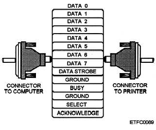
by a single parallel cable format (fig. 7-28). Other
signals that amid be used, but are not discussed,
include: page end, auto feed, error, initialize external
device (specific device name), and select input.
GROUND. —The ground signal ensures there is a
complete circuit so there is current, thus enabling the
signals to flow through the conductor and not collect at
one end of the circuit (conductor). There are two
grounds: one is a signal ground and the other a chassis
ground connected to the device’s chassis or ground.
These signals do not move in either direction.
DATA STROBE. —The data strobe is sent from the
computer to the external device. This signals the
Figure 7-28.—Single parallel cable.
external device that information is ready to be read from
the data lines. The computer first puts the signals for
all the data bits on the data lines, waits briefly to be sure
the signal is stable, and then activates the data strobe
line. When the external device sees that the data strobe
signal has been sent, it accepts the character from the
eight data lines.
BUSY SIGNAL. —The busy signal is sent from the
external device to the computer to tell it not to send any
more data. The external device may be busy for various
reasons. For example, it may still be in the process of
obtaining information or the buffer maybe full.
SELECT SIGNAL. —The select signal usually
corresponds to some sort of switch that must be in the
enabled position by the external device. An example is
an ONLINE switch on a printer. If it is disabled, the
computer will be able to sense that something is wrong.
ACKNOWLEDGE SIGNAL. —The acknowl-
edge signal is sent from the device to the computer to
say that it has successfully received information (a
character is this case).
Thus instead of sending
information at a constant rate, the computer waits for a
positive indication that each character has been received
before sending the next one.
DATA LINES. —Input/output data and interrupt
bits are sent or received from the computer on these
lines.
Single Cable Sequence of Events
The general sequence of events for a single cable
parallel operations is as follows:
1. The computer puts the character on the data
lines and sends the data strobe signal to tell the external
device the data is there.
2. As soon as the external device sees the data
strobe, it turns on the busy signal, telling the computer
to wait while it reads the character from the data lines
into its buffer.
3. Once the external device has processed the
character, it sends the acknowledge signal and
simultaneously removes the busy signal.
4. This tells the computer that it is all right to send
another character and the process is repeated.
7-32


