BIDFET—High voltage bipolar field-effect
transistor; MOS technology added to the BIFET
approach
N-FET—MOSFET N-channel FETs
BIDMOS—Diffused metal-oxide semicon-
ductor (DMOS) and bipolar technology
Lin CMOS—Silicon gate MOSFETs
Lin CMOS allows for linear and digital logic on
the same IC. See figure 4-30.
LINEAR IC GATES
The basic gate for a linear IC is an operational
amplifier (op amp). Its basic function is to increase the
power, current, or voltage applied to its inputs. It is the
basis for other amplifiers used in linear ICs. A typical
op amp has three basic characteristics as follows:
Very high gain
High input impedance
Low output impedance
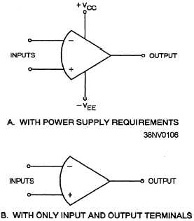
A typical op amp has two inputs called the
inverting input (–) and the noninverting input (+).
The inverting input provides a 180-degree phase shift
at the output. The noninverting input is in phase with
the output. Two power-supply terminals are provided.
They are usually called VCC (the collector terminal) and
Vee (the emitter terminal). This arrangement enables
Figure 4-31.—Example of an op amp: A. Shows power supply
requirements; B. Shows only input and output terminals.
the op amp to produce either a positive or negative
output. The schematic symbols for an op amp are
shown in figure 4-31. View A shows the power supply
requirements, while view B shows only the input and
output terminals.
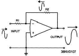
An op amp can have either a
close-looped operation or an open-looped operation
depending on its application. Refer to figure 4-32 for
an example of a closed-loop op amp.
LINEAR IC GROUPS
The linear ICs contained in a computer can be
classified into four groups: analog signal conversion
circuits, regulator integrated circuits, driver integrated
circuits, and line driver and receiver integrated circuits.
The operational amplifier is the key building block in
all of these linear ICs because of its ability to amplify
without the need for inductors or transformers. Basic
variations of the operational amplifier are included in
the classification of the four groups of linear circuits.
Analog Signal Conversion Circuits
Analog signal conversion circuits convert an
electrical or non-electrical variable to digital. These
linear circuits include analog-to-digital (A/D)
converters, comparators, memory drivers, sense
amplifiers, and timers.
Regulator Integrated Circuits
Regulator integrated circuits provide a constant
voltage or current supply. They can accomplish this
from a constant or variable power source. Regulator
integrated circuits include voltage regulators and
switching regulators.
Driver Integrated Circuits
Driver integrated circuits generate large voltage or
current output digital signals from small voltage and
Figure 4-32.—Example of a closed-loop op amp.
4-19


