binary-coded octal (BCO), groups of three LEDs or
lamps; binary-coded decimal (BCD), groups of four
LEDs or lamps; and binary-coded hexadecimal (BCH),
groups of four LEDs or lamps. Through man-machine
interfacing, the technician can directly interface with
the computer through the direct access of the registers
on the computer’s front panel.
Let’s look at the two types of registers most
commonly used throughout the computer—storage and
shift registers. Refer to figure 4-23.
Storage Registers. —General storage-type
registers do not alter the contents; by this we mean, what
enters the register is generally the same as what leaves
the register and is received by another register.
The transfer of data to and from a storage register
is done in parallel; all the data is transferred at the same
time. The methods used to transfer data in storage
registers are as follows:
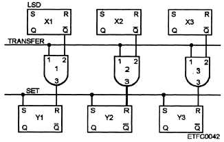
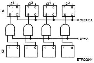
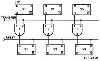
Single-line parallel transfer (direct method)—
Only 1’s or 0’s are moved in a bit-for-bit, order-for-
order method. The receiving register is cleared of its
contents before the transfer occurs.
If 1’s are
transferred, it is referred to as a one-side transfer. If 0’s
are transferred, it is referred to as a zero-side transfer.
See figures 4-24 and 4-25 as examples.
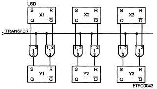
Double-line (dual) parallel transfer (also called
forced method)—1’s and 0’s are moved. This transfer
is faster than the single-line parallel transfer; however
it requires more logic gates. With this method the
receiving register is forced to assume the state of
corresponding flip-flops of the sending register. This
eliminates the need to clear the receiving register’s
contents before the transfer. Refer to figure 4-26.
Figure 4-24.—Example of a single-line parallel one-side
transfer.
Figure 4-25.—Example of a single-line parallel zero-side
transfer.
Figure 4-26.—Example of a double-line parallel transfer.
Complement —Similar to the single-line parallel
transfer except that the receiving register’s set side of
the flip-flops will receive the clear side of the sending
register’s flip-flops; thus the data has been
complemented after the transfer is complete. Refer to
figure 4-27.
Figure 4-27.—Example of a single-line parallel complement
transfer.
4-17


