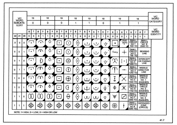
Figure 1-7.—The AN/UYA-4(V) symbol set.
Two different methods of painting symbols are
currently in use in the AN/UYA-4(V) display group.
They are the analog waveform and the digital stroke
methods. The symbols being generated are the same
in either case, only the methods used to generate the
symbols differ. Figure 1-7 shows the symbol set used
in the AN/UYA-4(V) display group.
The AN/UYQ-21(V) computer display set has an
expanded symbol set and develops sweep and
symbols using both the digital stroke method and
raster-scan CRTs, depending on the type of console.
Figure 1-8 shows the AN/UYQ-21(V) symbol set.
Analog Waveform Symbol Generation
To help you to
fully understand the analog
waveform generation process, we look at the
equipments required and the procedure that takes
place.
Analog symbols are formed by applying
harmonious waveforms to the deflection plates of a
CRT. For example, if two sine waves of equal
amplitude and 90-degrees out of phase are applied to
the X and Y axes of a CRT, a circle will be displayed
on the CRT. By adding the Z, or unblinking signal,
we can control what part of the circle is actually
displayed and thus form the symbol. Ellipses are
formed when the amplitudes of the two sine waves are
unequal.
Using the same principle with two trapezoid
waveforms that are 90-degrees out of phase, a square
will be formed.
1-8