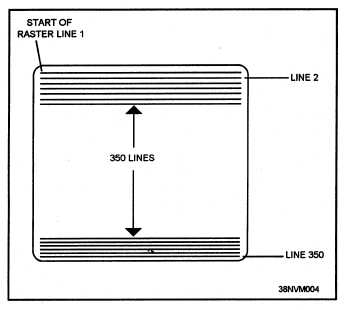
Figure 1-4.—Noninter1aced scan of a CRT.
Vector Scan
Vector scan CRTs are used extensively in the Data
Display Group
ANK/UYA-4(V) plan position
indicators (PPIs).
The circular display screens
provide control and display of conventional radar
sweep and video data and computer-generated
symbology.
The CRTs used in the PPIs use
electrostatic deflection
The methods used to
develop the deflection and unblinking signals for
radar sweep and video are similar because the same
CRT beam is used to develop both presentations.
However, the methods used to develop the radar
sweep and video are different from the two methods
used to develop symbology.
In the following paragraphs, you will learn how
the X/Y coordinate system is used to position the
CRT beam.
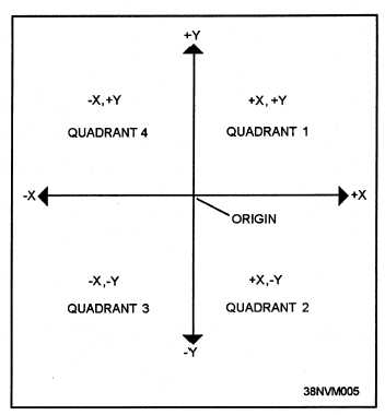
The X/Y coordinate system uses a grid as a frame
of reference. Figure 1-5 illustrates the concept of the
X/Y coordinate system. The horizontal line is the X
axis, and the vertical line is the Y axis.
The
intersection of the two lines is the origin of all
deflection signals. The origin is normally located at
the center of the CRT, but may be offset from the
center by operator action.
Figure 1-5.—The X/Y coordinate system.
The origin is the starting point for measuring
along both axes. To the right of the origin, values on
the X axis are positive; to the left, values are negative.
The values above the origin on the Y axis are positive;
below the origin, they are negative.
A point anywhere on the screen of the CRT may
be defined by two values: an X coordinate and a Y
coordinate. The X coordinate is used to develop the
horizontal deflection of the CRT beam. A positive X
value will move the beam to the right of the origin; a
negative X value will move the beam to the left of the
origin.
Vertical deflection is derived from the Y
coordinate value. A positive Y value will deflect the
beam upward from the origin, and a negative value
will move the beam down. The appropriate X and Y
values can be used to position the beam to any point
on the CRT. The combination of positive and
negative X and Y signals divides the CRT into the
four quadrants illustrated in figure 1-5.
A third signal is required to control the blanking
of the electron beam. The Z (unblank) signal is used
1-5