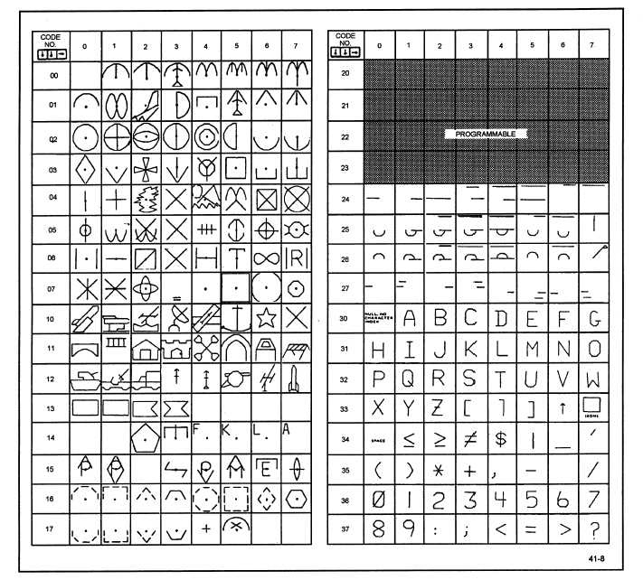
Figure 1-8.—The AN-UYQ-21(V) symbol set.
Symbols are defined by computer words. The
computer, using data input by the operator, determines
what symbol to display and where to display it on the
X/Y grid. It then puts together a digital message and
transmits it to a piece of ancillary display equipment
called a pulse amplifier/symbol generator (PA/SG).
Figure 1-9 illustrates how the pulse amplifier
interfaces the computer with the symbol generator and
the display consoles. It amplifies and distributes the
computer output data to the symbol generator and the
display consoles. The pulse amplifier also receives
computer input data from
sends it to the computer.
When a symbol message is sent to the display
equipment, the console takes control of the CRT
electron beam from the radar scan logic. It positions
the blanked CRT beam to the coordinates of the
symbol to be displayed and waits for the symbol
waveforms from the symbol generator.
The symbol generator develops the symbol
waveforms and timing pulses for the mechanization
(display) of the symbol. The timing pulses
synchronize the console’s painting of the symbol.
the display consoles and
Each symbol is composed of the following three
1-9


