Figure 9-1.—Centrifugal pump.
outlet. Figure 9-1 shows the arrangement of
components in a centrifugal pump.
CENTRIFUGAL PUMP CLASSIFICATION.—
Centrifugal pumps may be classified in several
ways. For example, they may be either single-stage
or multistage. A single-stage pump has only one
impeller; a multistage pump has two or more
impellers housed together in one casing. In a
multistage pump, each impeller usually acts
separately, discharging to the suction of the next-
stage impeller. Centrifugal pumps are also
classified as horizontal or vertical, depending on
the position of the pump shaft.
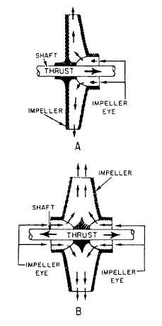
Impellers used in centrifugal pumps may be
classified as single-suction or double-suction,
depending on the way in which liquid enters the
eye of the impeller. Figure 9-2 shows single-
suction and double-suction arrangements of
centrifugal pump impellers. The single-suction
impeller (view A) allows liquid to enter the eye
from one side only; the double-suction impeller
(view B) allows liquid to enter the eye from both
sides. The double-suction arrangement has the
advantage of balancing the end thrust in one
direction with the end thrust in the other
direction.
Impellers are also classified as CLOSED or
OPEN. A closed impeller has side walls that
extend from the eye to the outer edge of the vane
tips; an open impeller does not have side walls.
Most centrifugal pumps used in the Navy have
closed impellers.
CONSTRUCTION.— As a rule, the casing for
the liquid end of a pump with a single-suction
impeller is made with an end plate that can be
removed for inspection and repair of the pump.
A pump with a double-suction impeller is generally
made so one-half of the casing may be lifted
without disturbing the pump.
Since an impeller rotates at high speed, it must
be carefully machined to minimize friction. An
impeller must be balanced to avoid vibration. A
close radial clearance must be maintained between
Figure 9-2.—Centrifugal pump impellers. A. Single-suction.
B. Double-suction.
9-2


