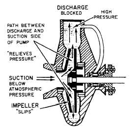
Figure 9-4.—Nonpositive-displacement pump.
centrifugal pump is usually located below the
liquid being pumped. (NOTE: This discussion
assumes a constant impeller speed.)
Figure 9-4 shows that when the pump dis-
charge is blocked, nothing happens because the
impeller is hollow. A tremendous buildup in
pressure cannot occur because the passages in the
impeller (between the discharge and suction side
of the pump) act like a built-in relief valve. When
the discharge pressure and pressure head are equal
(as in this case), the impeller is allowed to rotate
(slips) through the liquid in the casing.
NOTE: Centrifugal pumps used for inter-
mittent service may have to run for long periods
of time against a blocked discharge. Friction
between the impeller and the liquid raises the
temperature of the liquid in the casing and causes
the pump to overheat. To prevent this, a small
line is connected between the discharge and the
suction piping of the pump.
When a centrifugal pump is started, the vent
line must be opened to release entrained air. The
open passage through the impeller of a centrifugal
pump also causes another problem. It’s possible
for liquid to flow backwards (reverse flow)
through the pump. A reverse flow, from the
discharge back to the suction, can happen when
the pressure head overcomes the discharge
pressure of the pump. A reverse flow can also
occur when the pump isn’t running and another
pump is delivering liquid to the same piping
system. To prevent a reverse flow of liquid
through a centrifugal pump, a check valve is
usually installed in the discharge line.
NOTE: Instead of two separate valves, some
installations use a globe stop-check valve.
With a check valve in the discharge line,
whenever the pressure above the disk rises above
the pressure below it, the check valve shuts. This
prevents liquid from flowing backwards through
the pump.
MAINTENANCE.— You must observe the
operation and safety precautions pertaining to
pumps by following the EOP subsystem of the
EOSS—if your ship has EOSS. If not, use the
Naval Ships’ Technical Manual (NSTM) and/or
the instructions posted on or near each individual
pump. You must follow the manufacturer’s
technical manual or MRCs for PMS-related work
for all maintenance work. The MRCs list in detail
what you have to do for each individual mainte-
nance requirement.
Mechanical Seals.— Mechanical seals are
rapidly replacing conventional packing as the
means of controlling leakage on centrifugal
pumps. Pumps fitted with mechanical seals
eliminate the problem of excessive stuffing box
leakage, which can result in pump and motor
bearing failures and motor winding failures.
Where mechanical shaft seals are used, the
design ensures that positive liquid pressure is
supplied to the seal faces under all conditions of
operation and that there is adequate circulation
of the liquid at the seal faces to minimize the
deposit of foreign matter on the seal parts.
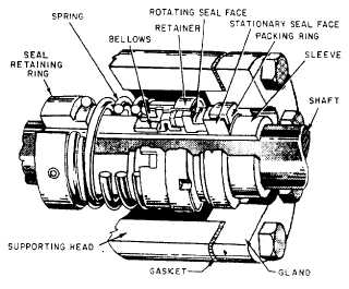
One type of mechanical seal is shown in figure
9-5. Spring pressure keeps the rotating seal face
Figure 9-5.—Type-1 mechanical seal.
9-4


