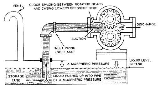
Figure 9-8.—Gear pump located above the tank.
Figure 9-8 shows a gear pump located above the
tank. The tank must be vented to allow air into
the tank to provide atmospheric pressure on the
surface of the liquid. To lower the pressure on
the suction side of the pump, the clearances
between the pump parts must be close enough to
pump air. When the pump starts, the air is
pumped through the discharge side of the pump
and creates the low-pressure area on the suction
side, which allows the atmospheric pressure to
force the liquid up the pipe to the pump. To
operate properly, the piping leading to the pump
must have no leaks or it will draw in air and can
lose its prime.
Rotary pumps are useful for pumping oil and
other heavy viscous liquids. In the engine room,
rotary pumps are used for handling lube oil and
fuel oil and are suitable for handling liquids over
a wide range of viscosities.
Rotary pumps are designed with very small
clearances between rotating parts and stationary
parts to minimize leakage (slippage) from the
discharge side back to the suction side. Rotary
pumps are designed to operate at relatively slow
speeds to maintain these clearances; operation at
higher speeds causes erosion and excessive wear,
which result in increased clearances with a
subsequent decrease in pumping capacity.
Classification of rotary pumps is generally
based on the types of rotating element. In the
following paragraphs, the main features of some
common types of rotary pumps are described.
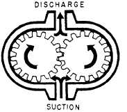
GEAR PUMPS.— The simple gear pump
(fig. 9-9) has two spur gears that mesh together
and revolve in opposite directions. One is the
driving gear, and the other is the driven gear.
Clearances between the gear teeth (outside
diameter of the gear) and the casing and between
the end face and the casing are only a few
thousandths of an inch. As the gears turn, the
gears unmesh and liquid flows into the pockets
that are vacated by the meshing gear teeth. This
creates the suction that draws the liquid into the
pump. The liquid is then carried along in the
pockets formed by the gear teeth and the casing.
On the discharge side, the liquid is displaced by
the meshing of the gears and forced out through
the discharge side of the pump.
One example of the use of a gear pump is in
the LM2500 engine fuel pump. However, gear
pumps are not used extensively on gas turbine
ships.
Figure 9-9.—Simple gear pump.
9-8


