opposite side), point c, and point d (opposite point
c). This action will show whether the coupling
faces are parallel to each other. If they are not
parallel to each other, adjust the driving unit or
the pump with shims until the couplings check
true. While measuring the distances, you must
keep the outside diameters of the coupling flanges
in line. To do this, place the scale across the two
flanges, as shown in figure 9-16, view C. If the
flanges do not line up, raise or lower one of the
units with shims, or shift them sideways.
The procedure for using a thickness gauge to
check alignments is similar to that for a scale.
When the outside diameters of the coupling
flanges are not the same, use a scale on the
surface of the larger flange, and then use a
thickness gauge between the surface of the smaller
flange and the edge of the scale. When the space
is narrow, check the distance between the coupling
flanges with a thickness gauge, as shown in figure
9-16, view D. Check wider spaces with a piece of
square key stock and a thickness gauge.
CONSTANT-PRESSURE
PUMP GOVERNORS
A governor is a feedback device that is used
to provide automatic control of speed, pressure,
or temperature. A constant-pressure pump
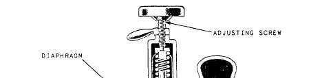
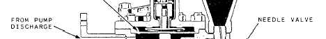
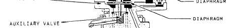
Figure 9-17.—Constant-pressure pump governor.
9-12