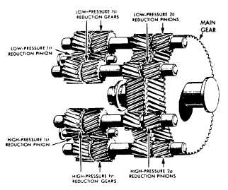
Figure 8-5.—Locked-train-type gearing.
ranges. A typical steam turbine reduction gear is
shown in figure 8-5.
The use of reduction gears is by no means
limited to ship propulsion. Other machinery, such
as ship’s service generators and various pumps,
also have reduction gears. In these units, as well
as in shipboard propulsion units, engine operating
efficiency requires a higher rpm range than that
suitable for the driven unit.
Reduction gears are classified by the number
of steps used to bring about the speed reduction
and the arrangement of the gearing. A gear
mechanism consisting of a pair of gears or a small
gear (pinion) driven by the engine shaft, which
directly drives a large (bull) gear on the propeller
shaft, is called a single-reduction gear. In this type
of arrangement, the ratio of speed reduction is
proportional to the diameter of the pinion and
the gear. For example, in a 2-to-1 single-reduction
gear, the diameter of the driven gear is twice that
of the driving pinion. In a 10-to-1 single-reduction
gear, the diameter of the driven gear is 10 times
that of the driving pinion.
Steam propulsion-type ships built since 1935
have double-reduction propulsion gears. In this
type of gear, a high-speed pinion, connected to
the turbine shaft by a flexible coupling, drives an
intermediate (first reduction) gear. This gear is
connected by a shaft to the low-speed pinion that,
in turn, drives the bull gear (second reduction)
mounted on the propeller shaft. A 20-to-1 speed
reduction might be accomplished by having a ratio
of 2-to-1 between the high-speed pinion and the
first-reduction gear, and a ratio of 10-to-1
between the low-speed pinion and the second-
reduction gear on the propeller shaft.
For a typical example of a double-reduction
application, let us consider the main-reduction
gear shown in figure 8-6. The high-pressure
and low-pressure turbines are connected to the
propeller shaft through a locked-train type of
double-reduction gear.
NOTE: This type of reduction gear is used
aboard many naval combatant ships.
First-reduction pinions are connected by
flexible couplings to the turbines. Each of the
first-reduction pinions drives two first-reduction
gears. A second-reduction (slow speed) pinion is
attached to each of the first-reduction gears by
a quill shaft and flexible couplings. These four
pinions drive the second-reduction (bull) gear that
is attached to the propeller shaft.
CLUTCHES AND REVERSE GEARS
Clutches are normally used on direct-drive
propulsion engines to provide a means of dis-
connecting the engine from the propeller shaft.
In small engines, clutches are usually combined
with reverse gears and are used for maneuvering
the ship. In large engines, special types of
clutches are used to obtain special coupling or
control characteristics and to prevent torsional
(twisting) vibration.
Diesel-propelling equipment on a boat or a
ship must be capable of providing backing-down
power as well as forward power. There are a
few ships and boats in which backing down is
accomplished by reversing the pitch of the
propeller. Most ships, however, back down by
reversing the direction of rotation of the propeller
shaft. In mechanical drives, reversing the
direction of rotation of the propeller shaft may
be accomplished in one of two ways. You can
reverse the direction of engine rotation or use the
reverse gears.
Reverse gears are used on marine engines to
reverse the rotation of the propeller shaft during
maneuvering without reversing the rotation of the
engine. They are normally used on smaller
engines. If a high-output engine has a reverse gear,
the gear is used for low-speed operation only and
does not have full-load and full-speed capacity.
For maneuvering ships with large direct-
propulsion engines, the engines are reversed.
The drive mechanism of a ship or a boat is
required to do more than reduce speed and reverse
8-4


