reservoir and/or sump and houses the accessory
drive gears and reduction gears.
The gear train is driven by the engine rotor
through an accessory drive shaft gear coupling.
The reduction gearing within the case provides
suitable drive speeds for each engine accessory or
component. The accessory drives are supported
by ball bearings assembled in the mounting bores
of the accessory case.
Accessories usually provided in the accessory
drive section include the fuel control (with its
governing device), the high-pressure fuel-oil pump
or pumps, the oil sump, the oil pressure and
scavenging pump or pumps, the auxiliary fuel
pump, and a starter. Additional accessories, which
may be included in the accessory drive section or
which may be provided elsewhere, include a
starting fuel pump, a hydraulic oil pump, a
generator, and a tachometer. Most of these
accessories are essential for the operation and
control of any gas turbine engine. However, the
particular combination and arrangement and
location of engine-driven accessories depend on
the use for which the gas turbine engine is
designed.
The three common locations for the accessory
section are on the side of the air inlet housing,
under the compressor front frame, or under the
compressor rear frame.
GAS TURBINE OPERATION
Naval engineers are constantly striving to
design a more reliable engineering plant that
provides quick response and requires fewer
personnel to operate it. With advances in
engineering technology, the use of solid-state
devices and the addition of logic and computer
systems, some of these design goals were achieved
in the automated central operating system
(ACOS).
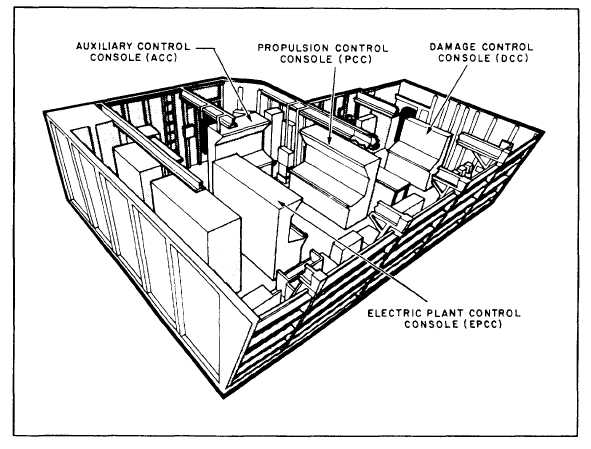
As shown in figure 6-22, ACOS centralizes the
engineering plant with all controls and indicators
located at the central control station (CCS). The
use of logic and computer systems reduces
Figure 6-22.—Typical central control station (CCS) for FFG-7 class ships.
6-15


