in (1) the type of blading material used, (2) the
means provided for cooling the turbine shaft
bearings, and (3) the lower ratio of blade length
to wheel diameter.
The terms gas-generator turbine and power
turbine are used to differentiate between the
turbines. The gas-generator turbine powers the gas
generator and accessories. The power turbine
powers the ship’s propeller through the reduction
gear and shafting.
The turbine that drives the gas generator is
located directly behind the combustion chamber
outlet. This turbine consists of two basic elements:
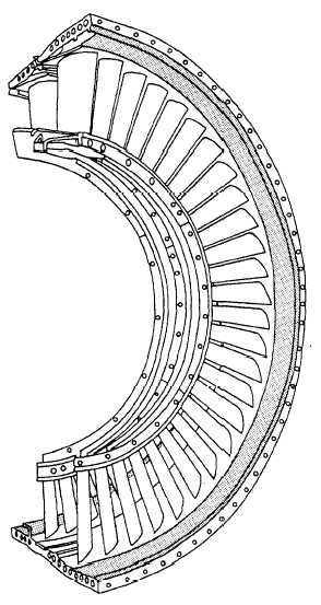
the stator or nozzle and the rotor. Part of a stator
Figure 6-19.—Stator element of turbine assembly.
element is shown in figure 6-19. A rotor element
is shown in figure 6-20.
The rotor element of the turbine consists of
a shaft and bladed wheel(s). The wheel(s) are
attached to the main power transmitting shaft of
the gas turbine engine. The jets of combustion
gas leaving the vanes of the stator element act
upon the turbine blades and cause the turbine
wheel to rotate in a speed range of 3,600 to 42,000
rpm, depending upon the type of engine. The high
rotational speed imposes severe centrifugal loads
on the turbine wheel. At the same time, the high
temperature (1050° to 2300 °F) results in a
lowering of the strength of the material.
Consequently, the engine speed and temperature
must be controlled to keep turbine operation
within safe limits. The operating life of the
turbine blading usually determines the life of the
gas turbine engine.
The turbine wheel is a dynamically balanced
unit consisting of blades attached to a rotating
disk. The disk, in turn, is attached to the rotor
shaft of the engine. The high-velocity exhaust
gases leaving the turbine nozzle vanes act on the
blades of the turbine wheel. This causes the
assembly to rotate at a high rate of speed. This
turbine rotation, in turn, causes the compressor
to rotate.
Figure 6-20.—Rotor element of turbine assembly.
6-13


