Compressor
The rotor and stators are enclosed in the
compressor case (fig, 6-16). Modern engines use
a case that is horizontally divided into upper and
lower halves. The halves are normally bolted
together with either dowel pins or fitted bolts.
These parts ensure proper alignment to each other
and in relation to other engine assemblies that bolt
to either end of the compressor case.
On some older engines, the case is a one-piece
cylinder open on both ends. The one-piece
compressor case is simpler to manufacture;
however, any repair or detailed inspection of the
compressor rotor is impossible. The engine must
be removed and taken to a shop where it can be
disassembled for repair or inspection of the
rotor or stators. On many split-case engines,
either the upper or lower case can be removed
for maintenance and inspection with the engine
in place.
The compressor case is usually made of
aluminum or steel. The material used will depend
on the engine manufacturer and the accessories
attached to the case. The compressor case may
have external connections made as part of the
case. These connections are normally used to
bleed air during starting and acceleration or at
low-speed operation.
Preceding the stators and the first stage of the
compressor rotor is a row of IGVs. The function
of the IGVs varies somewhat, depending on the
size of the engine and air-inlet construction. On
smaller engines, the air inlet is not totally in line
with the first stage of the rotor. The IGVs
straighten the airflow and direct it to the first-stage
rotor. On large engines, the IGVs can be moved
to direct the airflow at the proper angle to reduce
drag on the first-stage rotor.
Small and medium engines have stationary
stators. On large engines, the pitch of the vanes
on several stators can be changed. For example,
in the LM2500 engine (fig. 6-16) the first six
stators of the 16-stage rotor are variable,
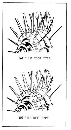
Rotor blades (fig. 6-17) are usually made of
stainless or iron-based, super-strength alloys.
Methods of attaching the blades in the rotor
disk rims vary in different designs, but they
are commonly fitted into disks by either bulb
(fig. 6-17, view A) or fir-tree (fig. 6-17, view B)
type roots. The blades are then locked with grub
screws, peening, lockwires, pins, or keys.
The stator vanes project radially toward the
rotor axis and fit closely on either side of each
stage of the rotor. The stators have two functions.
They receive air from the air inlet duct or from
each preceding stage of the rotor and then deliver
the air to the next stage or to combustors
at a workable velocity and pressure. They also
control the direction of air to each rotor stage to
obtain the maximum compressor-blade efficiency.
The stator vanes are usually made of steel
with corrosion- and erosion-resistant qualities.
Frequently, the vanes are shrouded by a band of
suitable material to simplify the fastening
problem. The vanes are welded into the shrouds,
and the outer shrouds are secured to the inner wall
of the compressor case by retaining screws.
Combustion Chambers
There are three types of combustion chambers:
(1) can type, (2) annular type, and (3) can-annular
type. The can-type chamber is used primarily on
Figure 6-17.—Rotor blades.
6-11


