The compressor draws in air at the hub of the
impeller and accelerates it radially outward by
centrifugal force through the impeller. It leaves
the impeller at high speed and low pressure and
flows through the diffuser (fig. 6-10, view A). The
diffuser converts the high-speed, low-pressure air
to low-speed, high-pressure air. The compressor
manifold diverts the low-speed, high-pressure air
from the diffuser into the combustion chambers.
In this design, the manifold has one outlet port
for each combustion chamber.
The outlet ports are bolted to an outlet elbow
on the manifold. The outlet ports ensure that
the same amount of air is delivered to each
combustion chamber.
The outlet elbows (known by a variety of
names) change the airflow from radial to axial
flow. The diffusion process is completed after
the turn. Each elbow contains from two to four
turning vanes that perform the turning process
and reduce air pressure losses by providing a
smooth turning surface.
AXIAL-FLOW COMPRESSOR
In the axial-flow engine, the air is compressed
while continuing its original direction of flow
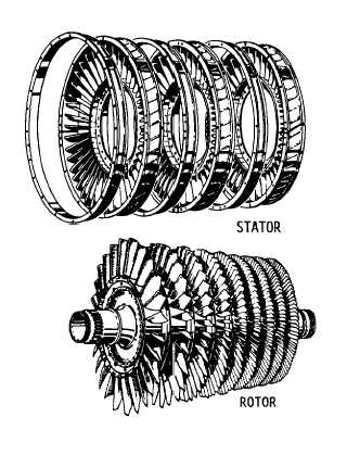
Figure 6-11.—Stator and rotor components of an axial-flow
compressor.
parallel to the axis of the compressor rotor. The
compressor is located at the very front of the
engine. The purpose of the axial compressor is
to take in ambient air, increase the speed and
pressure, and discharge the air through the
diffuser into the combustion chamber.
The two main elements of an axial-flow
compressor are the rotor and stator (fig. 6-11).
The rotor is the rotating element of the
compressor. The stator is the fixed element of the
compressor. The rotor and stator are enclosed in
the compressor case.
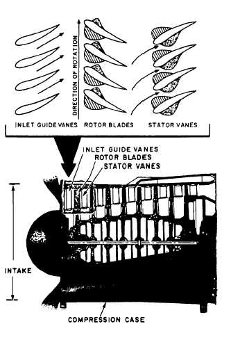
The rotor has fixed blades that force the air
rearward much like an aircraft propeller. In front
of the first rotor stage are the inlet guide vanes
(IGVs). These vanes direct the intake air toward
the first set of rotor blades. Directly behind
each rotor stage is a stator. The stat or directs the
air rearward to the next rotor stage (fig. 6-12).
Each consecutive pair of rotor and stator blades
constitutes a pressure stage.
Figure 6-12.—Operating principle of an axial-flow com-
pressor.
6-7


