The action of the rotor increases air
compression at each stage and accelerates the air
rearward. By virtue of this increased velocity,
energy is transferred from the compressor to the
air in the form of velocity energy.
The number of stages required is determined
by the amount of air and total pressure rise
required. The greater the number of stages, the
higher the compression ratio. Most present-day
engines have 8 to 16 stages.
CLASSIFICATION BY POWER USAGE
There are basically three types of gas turbines
in use. They are the single shaft, split shaft, and
twin spool. Of these, the single shaft and split
shaft are the most common in naval vessels. We
mention the twin-spool type because the U.S.
Coast Guard Hamilton class cutters use the twin-
spool gas turbine.
In current U.S. Navy service, the single-shaft
engine is used primarily for driving ship’s service
generators. The split-shaft engine is used for main
propulsion.
Figure 6-13 is a block diagram of a single-shaft
gas turbine. The power output shaft is connected
directly to the same turbine rotor that drives the
compressor.
In most cases, there is a speed
decreaser or reduction gear between the rotor and
the power output shaft. However, there is still a
mechanical connection throughout the entire
engine. The arrangement shown is typical for the
gas turbine generator sets aboard DD-963 and
CG-47 class ships.
In the split-shaft gas turbine (fig. 6-14), there
is no mechanical connection between the gas-
generator turbine and the power turbine. The
power turbine is the component that does the
usable work. The gas-generator turbine provides
the power to drive the compressor and accessories.
With this type of engine, the output speed can be
varied by varying the gas generator speed. Also,
under certain conditions, the gas generator can
run at a reduced rpm and still provide maximum
power turbine rpm. This greatly improves fuel
economy and also extends the life of the gas-
generator turbine. The arrangement shown in
figure 6-15 is typical for propulsion gas turbines
aboard the DD-963, FFG-7, CG-47, and PHM-1
class ships.
ENGINE CONSTRUCTION
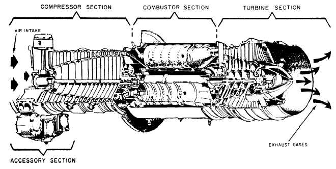
Recall that a gas turbine engine is composed
of four major sections (fig. 6-15): (1) compressor,
(2) combustor, (3) turbine, and (4) accessory. We
will briefly discuss the construction and function
of each of these sections. We will use the LM2500
gas turbine as an example. The LM2500 is a split-
shaft gas turbine.
Figure 6-15.—Typical gas turbine.
6-9


