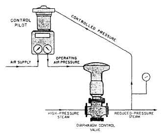
Figure 9-29.—Arrangement of control pilot and diaphragm
control valve for supplying reduced-steam pressure.
Figure 9-29 shows one arrangement that you
might use. Assume that the service requirements
indicate the need for a direct-acting, upward-
seating diaphragm control valve. Can you figure
out which kind of a control pilot—direct acting
or reverse acting—should be used in this
installation?
Try it first with a direct-acting control pilot,
As the controlled pressure (discharge pressure
from the diaphragm control valve) increases,
increased pressure is applied to the diaphragm of
the direct-acting control pilot. The valve stem is
pushed downward and the valve in the control
pilot is opened. This increases the operating air
pressure from the control pilot to the top of the
diaphragm control valve. The increased operating
air pressure acting on the diaphragm of the valve
pushes the stem downward, and since this is an
upward-seating valve, this action OPENS the
diaphragm control valve still wider. Obviously,
this won’t work for this application. An IN-
CREASE in controlled pressure must result in a
DECREASE in operating air pressure. Therefore,
we made a mistake in choosing the direct-acting
control pilot, For this particular pressure-reducing
application, you should choose a REVERSE-
ACTING control pilot.
It is not likely that you will be required to
decide which type of control pilot and diaphragm
control valve is needed in any particular installa-
tion. But you must know how and why they are
selected so you do not make mistakes in repairing
or replacing these units.
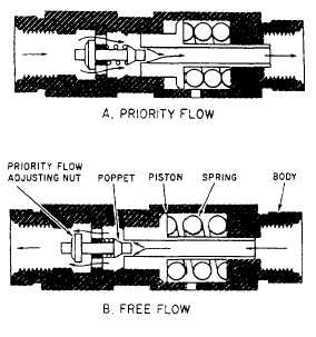
Figure 9-30.—Priority
PRIORITY VALVES.— In
valve.
systems with two
or more circuits, it is sometimes necessary to have
some means of supplying all available fluid to one
particular circuit in case of a pressure drop in the
system. A priority valve is often incorporated in
the system to ensure a supply of fluid to the
critical/vital circuit. The components of the
system are arranged so the fluid to operate each
circuit, except the one critical/vital circuit, must
flow through the priority valve. A priority valve
may also be used within a subsystem containing
two or more actuating units to ensure a supply
of fluid to one of the actuating units. In this case,
the priority valve is incorporated in the subsystem
in such a location that the fluid to each actuating
unit, except the critical/vital unit, must flow
through the valve.
Figure 9-30 shows one type of priority valve.
View A of figure 9-30 shows the valve in the
priority-flow position; that is, the fluid must flow
through the valve in the direction shown by the
arrows to get to the noncritical/vital circuits or
actuating units. With no fluid pressure in the
valve, spring tension forces the piston against the
stop and the poppet seats against the hole in the
center of the piston. As fluid pressure increases,
the spring compresses and the piston moves to the
right. The poppet follows the piston, sealing the
hole in the center of the piston until the preset
pressure is reached. (The preset pressure depends
upon the requirements of the system and is set
by the manufacturer.) Assume that the critical/
vital circuit or actuating unit requires 1500 psi.
9-20