THE 3.5-INCH FLOPPY DISK
CONSTRUCTION
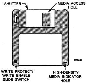
Figure 10-6 shows a 3.5-inch disk. The 3.5-inch
and 5.25-inch disks are constructed of the same basic
materials. The disk is a thin flexible polyester film base
that is coated with a magnetic compound. This
compound is iron-oxide for standard and double-
density disks and a cobalt ferric compound for high-
density disks.
Disk Case
The 3.5-inch floppy disk’s rigid plastic case
stabilizes the disk as it spins. This allows for greater
densities of data to be written on the disk.
Media Access Hole and Shutter
Examining the case of a 3.5-inch disk, you’ll notice
several differences from the 5.25-inch disk. The first
difference is the metal shutter covering the media access
hole. This shutter is spring loaded and moves out of the
way to expose the disk when the disk is loaded into a
drive. When the disk is not loaded in a drive, this shutter
covers the hole and eliminates the need for a disk jacket
to store the disk.
Write Protect/Write Enable Slide
Write protection for the disk is accomplished by
means of a slide switch in the lower left comer of the
disk. Figure 10-6 illustrates the location of the write
protect/write enable slide switch. When the slide
switch is positioned so you can see a hole through the
case, the disk cannot be written on.
Media Indicator Hole
On the lower right corner of some 3.5-inch disks is
another hole that designates the disk as a high-density
disk. When a high-density disk is loaded into a
high-density drive, a sensor checks for the presence of
this hole. If it is present, the disk can be formatted in
the 1.44M mode. If this hole is not present, the disk can
only be formatted as a 720K disk.
FLOPPY DISK DRIVE OPERATION
Several basic components are common to all floppy
disk drives. To properly test, install, or service a disk
drive, you must be able to identify these components
and understand their functions in the drive. Figure 10-7
shows a typical 5.25-inch disk drive with the major
components labeled as follows:
Spindle assembly/drive motor
Drive electronics circuit board
Connectors
Head actuator assembly
Read/write head arm assembly
Spindle Assembly/Drive Motor
Figure 10-6.—The 3.5-inch floppy disk.
The spindle holds the disk in place while it spins.
The drive motor spins the spindle at the proper speed.
Most floppy disk drive motors spin at 300 rpm except
the 1.2M drive, which spins at 360 rpm. Almost all
half-height drives use a direct drive motor to turn the
spindle, and the speed cannot be adjusted.
Some older Ml-height drives use a belt-driven
motor. These belt-driven drives usually have a
strobo-disk mounted on the underside of the drive set
to both 50 Hz and 60 Hz. To adjust the speed, you
remove the drive and issue a command to get the motor
running. Look at the strobo-disk under a fluorescent
light and adjust the drive speed until the outer
strobo-disk spokes appear to be standing still. The inner
disk is setup for 50 Hz operation, the frequency of
European main power.
10-8


