its bistable nature. Two paired thin film spots are used
for each bit position.
Like magnetic core memory,
mated film memory uses bistable magnetic material as
a means of recording binary data. A film spot is
magnetized by current flow through the word line or
sense/digit line.
A film spot magnetized in one
direction represents a binary zero, and when
magnetized in the opposite direction represents a binary
one. Figure 6-14 shows the bistable nature in thin film
spots. As stated, a film spot is magnetized by current
flow through the conductor (word line or sense/digit
line). The preferred direction of magnetization is
known as the easy (longitudinal) axis of the film
because dipole alignment along this axis is stable. The
axis perpendicular to the easy axis is referred to as hard
(transverse) axis because dipole alignment along this
axis is unstable and will fall to a stable state upon
removal of the polarizing magnetic field.
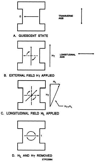
The method of switching states in a mated film
memory cell is referred to as coherent rotation. In
coherent rotation, each magnetic dipole is rotated in
unison with an applied field. A thin film can be
switched as fast as external fields can be applied and
removed. Figure 6-15, frame A, shows a film in the
quiescent state, the magnetization is along the easy axis,
and no external fields are applied. In frame B of figure
6-15, an external field is applied perpendicular to the
easy axis. If the transverse field (HT) is large enough,
the magnetic vector will rotate to the hard axis position.
As illustrated in figure 6-15, frame C, a small
longitudinal field (HL) is applied in the same direction
as the desired zero or one easy axis, by applying current
in the proper direction to the sense/digit line.
Combining the HL field with the HT causes the
magnetic vector to rotate beyond the hard axis to the
desired polarization for a zero or a one. When the HL
and HT fields are removed, the magnetic field falls or
rotates (fig. 6-15, frame D) to the stable one state along
the easy axis.
In figure 6-16, the method for applying an external
field to the thin film elements is shown. Transverse
fields are produced by passing current down the word
line. Longitudinal fields are produced by passing
current in the proper direction along the sense/digit line.
When a current is passed through either conductor, a
magnetic field is induced around the conductors as
shown. Current through the word line will apply a
transverse field to each element. The transverse field is
concentrated on each film spot by a magnetic keeper.
Current through the sense/digit line applies a
longitudinal field in one of two directions to each film
element. Each film element is physically separated
Figure 6-15.—Film architecture: A. Quiescent state; B.
External field HT applied; C. Longitudinal field HL
applied; D. HL and HT removed.
from the sense/digit line by a thin layer of electrical
insulation.
PACKETS. —Film spots are organized by
packets; the packets form a stack. Each packet can
store two binary bits (zero or one) of data. Two paired
thin film spots are used for each bit position. The
purpose of the second film is to act as a keeper to the
first film. This makes the mated film cells less
susceptible to the disturbance from other cells in close
proximity to them. The word pair line, sense/digit line,
and keeper through each packet allow for the reading
and writing of data in film. A packet consists of the
following:
6-14


