method for determining the position of a point, a line,
a curve, or a plane in a space of given dimensions,
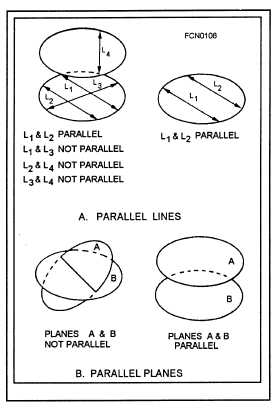
called a reference frame. Figure 3-1 shows typical ex-
amples of parallel lines and planes.
Figure 3-1.—Typical examples of
parallel lines and planes.
Ultimately, the alignment of parallel lines, parallel
planes, and coordinate systems is used to establish a
pointing line for each piece of equipment in the ship’s
combat system. The line representing the direction in
which apiece of equipment is pointing is the pointing
line of that equipment. As previously indicated, the
pointing line may be the bore axis of a gun, the line of
sight of a director, or the propagation axis of a radar
beam. Accurate alignment is not possible unless the
pointing line is precisely determined.
FRAME OF REFERENCE
The reference point, the reference direction, and
the reference plane form a geometric structure called
the reference plane. In the complete reference frame,
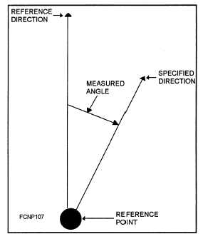
directions are specified by two angles (train and ele-
vation), measured about the reference point. Figure
3-2 shows the measurement of an angle from a refer-
ence direction.
Figure 3-2.—Measurement of an angle
from a reference direction.
A geometric measurement is based on a definite
and complete set of geometric references. To permit
clear and accurate definition of target position, a
definite point on the ship (such as a director) is
selected as the starting point for the measurement. As
a reference point, a director center of rotation is
selected arbitrarily because the director has interface
with all the major equipment of a battery. Once the
reference point is determined, it becomes apart of any
future measurement made from it and must be clearly
specified before subsequent measurements have any
meaning.
Once the reference point is selected, a reference
direction is established from which train angles are
measured. Train angles are measured about the refer-
ence point, beginning at the reference direction. In
naval combat systems, the ship’s centerline, which
points in the direction of the bow, is used as the refer-
ence direction.
Angles expressing direction cannot be described
unless a means is available for specifying the plane in
3-2