which the angle is to be measured. This plane is re-
ferred to as the reference plane and maybe any plane
convenient for use. The horizontal plane is one of the
most commonly used reference planes because of the
ease of using a spirit level or similar device to deter-
mine the plane. In naval combat systems, the refer-
ence plane is parallel to the reference element (the
director) roller path. Whichever plane is selected for
reference, it must be clearly specified before subse-
quent measurements are of any significance. When
the reference plane is used, a means must be esta-
blished to denote the top of the plane to express the
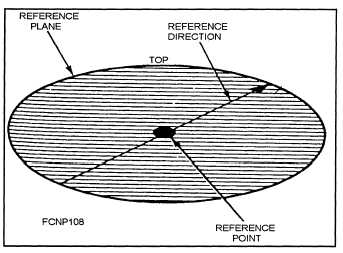
angle correctly. Train angles are measured clockwise
from the reference direction on the top of the plane.
Figure 3-3 shows a typical reference plane.
of commission. In such an event, you must be able to
use the target data from either of the directors to get a
fire-control solution. To interpret data measured in
different frames, you must know how the frames are
Figure 3-3.—Typical reference plane.
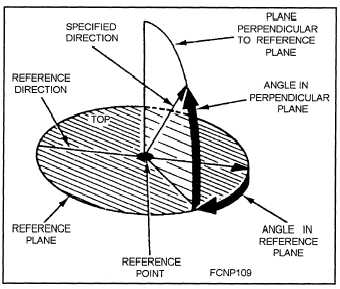
The elevation angle is in a plane perpendicular to
situated with respect to each other. Figure 3-4 is
representation of a complete reference frame.
the horizontal reference plane and is measured from
the reference plane. The concept of a reference frame
is important in the expression of a direction and the
problems related to alignment. The reference point is
a definite point aboard ship, and the reference plane
and the reference direction have a definite orientation
in respect to the reference point.
In fire control, it is often necessary to operate
simultaneously with two or more reference frames.
(For instance, these frames might be situated in dif-
ferent parts of a ship.) It maybe desirable to measure
target data with several directors because of a need for
flexibility in controlling different fire-control systems
to obtain a wide range of view or if one director is out
Figure 3-4.—Representation of a
complete reference frame.
The difference or displacement between two
frames may be of two kinds—linear and angular.
Linear Displacement
Linear displacement is the distance between two
reference frames measured between their reference
points. This displacement may be in the vertical direc-
tion, the horizontal direction, or both.
The corrections made necessary by the linear
displacement between the reference points are called
parallax corrections and are considered separately
from corrections arising from the rotation between the
frames. Parallax corrections can be separated into
either dynamic parallax corrections or static parallax
corrections.
DYNAMIC PARALLAX CORRECTIONS.—
Position quantities computed for the reference frame
3-3


