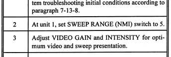
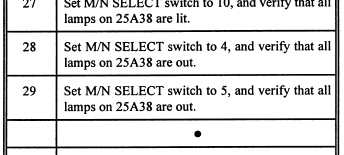
Table 1-8.—Sample Video Processing
and Distribution System Checkout Procedures
In our sample troubleshooting problem, the faulty
component is Test Board 25A38A31. To isolate this
component, the technician performs the checkout
procedures shown in table 1-8. At step 27, the tech-
nician observes that none of the lamps on 25A38 are
lit. From here, the technician proceeds to the problem
directory (see table 1-9), step 27, where he is directed
to set the S/P BYPASS switch to ON. After doing
this, he notices that more than one lamp is out on
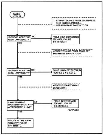
25A38. The problem directory refers the technician to
the incorrect lamp indicator pyramid diagram, shown
in figure 1-8.
Figure 1-8.—Incorrect lamp pyramid diagram 7-13-2.
Here, the technician follows the instructions out-
lined in the dashed blocks and answers the questions
in the solid block. Eventually, the technician is in-
structed to measure the voltage at 25A38A3lTPI. A
zero-voltage reading at this test point indicates that
Test Board 25A38A31 is the faulty component. The
technician replaces the circuit board and verifies
correct operation by repeating step 27 in the checkout
procedures.
Figure 1-9 is a sample troubleshooting system
fictional diagram.
1-22


