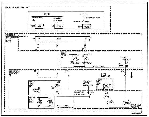
Figure 1-7.—Relay lamp ladder diagram.
The relay lamp ladder diagram is a troubleshoot-
ences in fire-control equipment, each fire-control sys-
ing support document for the signal-flow diagram and
tern has its own troubleshooting philosophy. How-
the maintenance turn-on procedure. It is also used as
ever, they all use the basic troubleshooting documen-
the prime troubleshooting document for equipment
tation (or a modification or combination of the basic
switching problems.
documentation) covered in this chapter.
The relay lamp ladder diagram traces the energiz-
ing path for the relay coil or indicator lamp from a
common interface point appearing on both the power-
distribution diagram and the ladder diagram. It traces
through the equipment, to the respective relay coil or
indicator lamp, and to a common return power inter-
face. The relay lamp ladder diagram shows cabling,
terminal connections, relay contacts, switches, and
lamps in the energizing path.
SAMPLE EQUIPMENT TROUBLESHOOT-
ING PROBLEM.— Because of the inherent differ-
This sample problem uses the checkout procedure,
and the problem-directory and pyramid-diagram
methods of troubleshooting. In these methods, the
technician sets up, adjusts, and verifies equipment
operation according to a set of steps in the checkout
procedures shown in table 1-8.
If the function being tested at a particular step
fails, the technician refers to that same numbered step
in the problem directory to isolate the faulty compo-
nent. A sample problem directory is shown in table
1-9.
1-21


