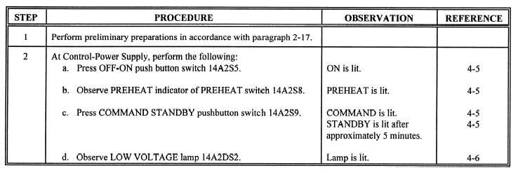
Table 1-6.—Sample Maintenance Turn-On Procedures
Some of the primary equipment troubleshooting
may also include internal indications at key test
documentations are covered in this subsection, includ-
ing fault logic diagrams, signal-flow diagrams, pyra-
mid diagrams, relay and lamp indexes, and relay lamp
ladder diagrams. Also included is a sample equipment
troubleshooting problem relating to a simple checkout
procedure.
FAULT LOGIC DIAGRAMS.— Fault logic dia-
grams (FLDs) are used to speed troubleshooting by
requiring the technician to answer a branching series
of questions about an observed system fault. The
questions, which permit only yes-or-no answers, per-
tain primarily to the status of external indications
(lamps, dials, meters, scope displays, etc.), but they
points. By a process of elimination, the technician is
led to the area of probable trouble and is referred to
equipment troubleshooting documents. Figure 1-4
shows a sample fault logic diagram.
SIGNAL-FLOW DIAGRAMS.— Signal-flow
diagrams show the signal flow from an input to an
output function. Adjustment procedures, replacement
procedures, and schematics are referenced in the
signal-flow diagram to provide the technician with
quick access to the appropriate maintenance require-
ment cards and related troubleshooting documenta-
tion. Figure 1-5 shows a sample signal-flow diagram.
1-17


