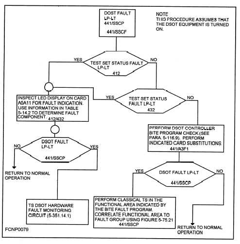
PYRAMID DIAGRAMS.— Pyramid diagrams
pertain to the interdependency of the subassemblies
essential to each function of a piece of equipment.
The pyramid starts with an output function and, for a
given local test setup, lists the values and allowable
tolerances of that function. Subsequent checks of the
various inputs that affect the function are contained in
blocks, which radiate downward from the statement of
The blocks contain recommended corrective
action if the check of the input is at fault. Each leg of
the pyramid is terminated by an input and a reference
to other pyramids or related documents. Thus, the
equipment troubleshooting pyramids should enable
the technician to quickly localize faults and perform
the necessary corrective action by referencing the
associated material. Figure 1-6 shows a sample pyra-
mid diagram.
the function.
Figure 1-6.—Pyramid diagram.
RELAY AND LAMP INDEXES.— The relay
switches and indicator lamps. They cross-index (by
and lamp indexes list all the relays and lamps shown
figure, sheet, and zone) the location of the relay coil
on the troubleshooting diagrams. The indexes list, in
and indicator lamp energizing paths. Table 1-7 shows
unit designation sequence, all relay coils and related
a sample relay index.
1-19


