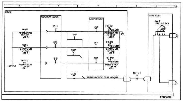
System Functional Diagram
mally from left to right. All serial components of each
piece of equipment in the loop that are significant to
A system fictional diagram (SFD) contains all
functional understanding are shown. All readout
primary and secondary circuits necessary for an
devices, test points, etc., in each equipment that are
understanding of the function of a particular mode,
significant to system troubleshooting are included on
loop, or phase of system operation. Each function is
the SFD. A sample weapons system fictional dia-
shown from source to termination. Data flow is nor-
gram is shown in figure 1-3.
Figure 1-3.—Sample weapons system functional diagram.
Fault Analysis Matrix
Associated switchboards are setup correctly,
all power lamps are lit, and no fuses are blown.
The fault analysis matrixes (FAMs) and their
associated troubleshooting procedures are related to
each other and to the SMTs. Together, they provide
maintenance personnel with an effective troubleshoot-
ing package.
To keep this material as specific as possible, the
following assumptions are made:
All equipment has been properly energized
and indicator lamps have been tested.
Troubleshooting faults do not begin until the
test is completed, if possible. This procedure allows
the technician to troubleshoot several related faults
simultaneously, reducing troubleshooting time.
Troubleshooting faults should occur in the
same sequence in which the faults are discovered; for
example, a fault discovered in step 9 of an SMT
should be corrected before a fault discovered in step
14. Adherence to this sequence for correcting faults is
1 - 1 4


