as the preamble.
The principal function of the
preamble is to alert the receiver of incoming data and
provide a reference to synchronize the receiver with
the transmitted signal. Following the preamble is a
start code that informs the receiving equipment of the
beginning of the message data. The basic format of
the synchronous data message is shown in figure 1-3.
The incoming bit stream is then used to synchronize
the receiver or demodulator timing. A stop code
follows the message data to indicate the end of
transmission.
MODULATION/DEMODULATION
Modulation modifies a signal so it can carry data
over the communications channel. The demodulator
removes the data from the carrier. For most data
communications applications, the carrier is a
continuous sinusoidal waveform (sine wave). The
frequency of the carrier varies, depending on the
application. Landline transmission generally uses the
audio-frequency bandwidth signals (300 to 3,000 Hz).
Radio channels use audio-frequency tones as data
carriers modulated to a radio-frequency signal, or they
modulate the radio-frequency signal itself to convey
data.
The three basic modes of modulation are
amplitude modulation, frequency modulation, and
phase modulation. Each of these modes modifies the
carrier signal in some manner to convey data.
Amplitude Modulation
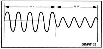
When amplitude modulation is used for digital
transmissions, the amplitude of the carrier signal
represents the two discrete data states (1 or 0). The
signal represents a logic 1 when the amplitude
(peak-to-peak), at the same frequency, is greater at a
different time, as shown in figure 1-4. The decrease
in signal amplitude, below a predetermined threshold,
indicates a change from a logic 1 to a logic 0.
Frequency Modulation
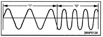
The frequency of the carrier signal or audio tones
modulated to the carrier signal can be modified to
indicate the two discrete states. As shown in figure
Figure 1-4.—Amplitude modulation.
1-5, a selected frequency can be used to indicate the
1 state of a bit, and another selected frequency can be
used to indicate the 0 state. The change in frequency,
or frequency shift, indicates the same relationship as
the change in amplitude did in amplitude modulation.
Figure 1-5.—Frequency modulation.
Shifting the frequency of the carrier signal is
called frequency-shift keying (FSK) or binary
frequency-shift keying (BFSK).
FSK usually
involves shifts to frequencies above or below a
selected center frequency.
Transmission of the
frequency above the center frequency indicates a
binary 1; the frequency below the center frequency
indicates a binary 0.
The center frequency is not
transmitted. FSK is used in systems such as link 4A.
Another method of using frequency shifts involves
audio-frequency tones. Two discrete audio tones may
be modulated to a constant frequency carrier signal.
One of the tones is used to indicate a mark, or binary
1, the other a space, or binary 0. This method of
frequency modulation is called audio-frequency tone
shift (AFTS).
Phase Modulation
Phase modulation is
modulation. It is based
1-6
a more complex mode of
on the relationship of the


