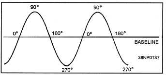
360-degree carrier sine wave to the baseline of the
sine wave. The carrier signal starts on the baseline, as
illustrated in figure 1-6, and continues to form a curve
called the sine wave. When the sine wave reaches its
maximum positive amplitude, it is at the 90-degree
point. When it returns to the baseline, it is at 180
degrees. When it reaches its maximum negative
amplitude, it is at 270 degrees; and when it returns to
the baseline, it is at 360 degrees or the 0-degree point
for the start of the next cycle. This process occurs
over a period, with the number of full cycles per
second (Hz) being the frequency of the signal. A full
cycle is the transition from the 0-degree point to the
360-degree point.
Figure 1-6.—Carrier sine wave,
For a particular frequency this process continues
without interruption.
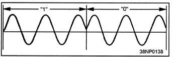
Phase modulation involves
interrupting the cycle at one or more degree points
and instantaneously changing the direction or
amplitude of the sine wave. Figure 1-7 shows how a
180-degree phase shift is used to indicate two discrete
states. The third cycle of the carrier is interrupted at
the 180-degree point. Instead of continuing in the
negative direction, the sine starts at the 0-degree point
again. The resultant signal has the same frequency
and amplitude as the original signal but is 180 degrees
out of phase. This phase shift can be directly related
to a digital input at a modulator in which one
particular phase represents the 0 bit and the other
phase represents the 1 bit.
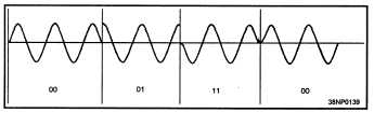
Multibit Modulation
While the 180-degree phase shift can be used to
indicate two discrete states, many points on the sine
wave can be defined to represent different bit
configurations.
Individual phase changes of 0
degrees, 90 degrees, 180 degrees, and 270 degrees
from a reference phase can each represent two
separate data bits. For example, a 0-degree phase
shift or no phase shift could indicate a binary 00; a
90-degree phase shift, a binary 01; a 180-degree phase
shift, a binary 10; and a 270-degree phase shift, a
binary 11. This type of modulation is known as a
multibit, or quadrature (four-state) phase-shift
modulation, as shown in figure 1-8. Keep in mind
that only one continuous frequency and amplitude
signal is being phase-modulated to transmit two bits
of data for each phase shift.
Figure 1-8.—Multibit phase modulation.
A modification of the quadrature phase-shift
modulation,
called
differential
quadrature
phase-shift keying, uses the difference between a
phase-shifted signal and its preceding sine wave to
represent data. When a phase shift is detected, the
current signal is compared with the previously
transmitted phase signal. The difference between the
two signals is computed to determine the amount of
phase shift. The previously transmitted signal is used
as the reference phase for demodulating the data bits.
Two binary digits are represented by phase changes of
-45, -135, -225, and -315 degrees. The -45 degree
shift indicates a binary 11; the -135 degree shift, a
binary 01; the -225 degree shift, a binary 00; and the
-316 degree shift, a binary 10.
Figure 1-7.—Phase modulation.
1-7