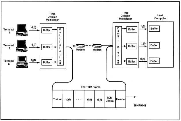
Figure 1-10.—A time-division multiplexer (TDM) system.
the decoder. The decoder reassembles the data into a
be designated in a single modulation change. If two
form compatible with the receiving system. In the
receiver section, the incoming signal is often fed to
the receiver timing logic to control the receiver timing
circuitry.
MULTIPLEXING
One requirement of a data communications system
is for it to transmit as many intelligent signals as
possible in a fixed period using a single-
communications channel.
The rate of data
transmission is measured in the number of bits per
second (bps) transmitted. The bps rate is often
confused with the baud rate. Baud refers to the rate at
which a modulated signal between two devices
changes in 1 second.
For example, if the signal
between two modems changes frequency or phase at
a rate of 2,400 times per second, the baud is 2,400. If
you are using a modulation method in which a single
modulation change carries one bit, the 2,400 baud is
also 2,400 bits per second. Using more sophisticated
modulation methods, several bits of information can
bits of data are transmitted with each modulation
change, the data transfer rate is 4,800 bits per second
at 2,400 baud.
The data signals being transmitted are normally
multiplexed to increase the transmission rate of data
over the communications channel or to increase the
efficiency of the channel by allowing multiple users
of the same channel. The two methods commonly
used to multiplex communications channels are
time-division multiplexing and frequency-division
multiplexing.
Time-Division Multiplexing
Time-division multiplexing (TDM) grants each
user full channel capacity, but assigns time slots to
each user. Each user is connected to a time-division
multiplexer. Data signals from the user are fed to the
time-division multiplexer buffer, and the time slots
are rotated among the users and scanned for data.
Figure 1-10 illustrates the typical construction of a
1-9


